中心议题:
* 现场总线和工业网络
* 现场总线类别
* 工业自动化现场总线
现场总线是允许将用于分布式控制、监测、检测和管控的设备互连起来的通信系统。得益于这项技术,传感器、电磁阀、可编程控制器、电子驱动器和电脑等,可以很容易地使用一个单一的低成本互连交换信息。这种信息交互不依赖于任一设备制造商。

图1 - 多种设备可以连接到现场总线进行数据交换。
注:Marcatori laser=激光打标机;Servoazionamenti=伺服驱动器;Sistemi di polimerizzazione =聚合系统;Unità wireless=无线单元;Termoregolatori=温机;PLC ultra-compatti =超小型PLC,Pannelli operatore=操作面板;Sensori fotoelettrici=光电传感器;Ionizzatori=负离子空气净化器;Sistemi di visione=机器视觉系统;Sensori laser=激光传感器;Barriere di sicurezza=安全光栅。
现场总线的概念并不新鲜,但近年来,基于如下两个原因,它倍受欢迎:一是相关商业行为的增多;二是用户已经理解这项技术所带来的明确战略价值。
为什么对现场总线的兴趣会高涨呢?很大程度上是因为,市场需要使用不同的产品,同时又不希望有任何商业或技术限制。供应商本身明白一个公共环境的益处:若一款产品配备着标准接口,这意味着它拥有更广阔的市场。
‘现场’一词有地理上和内容上界定的意蕴。即使在“现场总线”的定义上,在不同的抽象层面,也是如此。另一方面,“总线”一词,是计算机科学领域的典型用语,用以指代连接不同电路、使其能交换数据的一组导线。因此,现场总线是一种通信系统,其目的是连接多个积极参与数据交换的分布式设备。
一般来说,现场总线允许以串行方式一位接一位地传输数据。这种方案的好处是:可极大减少所需导线的数量(通常,现场总线只有三根电导线)。这一方案允许以低成本覆盖远距离。
这种通信系统的正确操作要求对现场总线的访问遵循严格规则,以便信息流可以从生产者流通到消费者。这些规则被称为“协议”。

图2 - 像所有标准化的通信网络一样,现场总线也遵循ISO/OSI协议栈。
基本上,现场总线的主要优势是以下两个方面:
- 通过现场总线实现的信息交换,若借助其它方式将难以实现
- 信息交换遵循标准化的机制
从以上两点还衍生出了其它的一些优势,它们目前已得到广泛的商业应用:
- 基于现场总线的网络可以很容易地扩展
- 不同厂家的产品可以“对话”
- 可以覆盖更远距离
- 布线和整体成本大幅降低
- 应用领域更宽广
- 安装得到了简化
- 工程成本是可重利用的
- 市场提供监测和调试工具,使上述这些任务更容易
但也应提到现场总线的一些不足之处:
- 需要更深厚的技术积累
- 需要更大的设备和仪器投资
- 更高的起步成本
- 不能确保不同厂家设备间的兼容性,虽然它们使用相同标准。
与各行业息息相关
当今,每个人都与现场总线息息相关。以汽车为例,现场总线被用来简化布线、并为基本控制增加了功能。但这个例子表明,从最终效果看,最终用户并非真的很关注实际所使用的现场总线。
除最终用户外,还有其他两类专业人士与现场总线有关:
- 使用能够通过现场总线进行通信的设备的系统集成商,必须承担调试工作
- 现场总线设备或通信接口的开发商,要有能力开发电子硬件和适当的软件
这两类专业人士解决所面临问题的方式不同。对第一类系统集成商来说,重要的是拥有可使调试和诊断更容易的工具。此外,现场总线最好是易于使用。另一方面,对第二类总线及产品开发者来说,更重要的是找到可最大程度简化——电子电路和通信管理软件研发——的电子元器件。
现场总线类别
在为特定任务选择通信网络时,先进行分析很有帮助,该分析可能没有商业方面的考虑。 “金字塔”模型对分析任务有实际贡献。
理想的工厂会有多层次的数据管理。每个层次的要求不同。例如,管理部门通常会处理以兆字节为单位的数据,但响应时间不是关键因素(可以是几分钟、几小时、甚至几天)。
但在工作车间和生产领域(现场总线的主要战场),会有更多限制:在最底层水平,要考虑到另一端的情况,必须在几微秒内传送几个字节。
一般会定义如下的通信等级:
- 层级0:‘传感器/执行器’总线
- 层级1:现场总线
- 层级2:单元总线
- 层级3:局域网(LAN)
- 层级4:广域网(WAN)

图3 - 工厂建筑内的现场总线定位:现场总线通常涉及层级0、1和2。
这些差异也是选择现场总线类型的标准。一般情况,对于特定应用,可以容易地量化诸如响应时间和可传送的数据量等参数。
现场总线层级只涉及“金字塔”模型的最底层。这一层级包括所有可传送从几位到几百字节数据帧的总线。现场总线层级可进一步分为3个主要组别:
- 实际现场总线
- ‘传感器/执行器’总线,专用于I/O信号互连(‘复用器’功能)
- 针对特定应用的总线(例如:Sercos等运动控制总线;LON等建筑自动化总线;LIN等汽车总线。)
真正的现场总线用于连接在一个过程中协同工作的智能单元。这个级别的应用,通常以分层次的方式建构,大多此类通信的现场总线遵从“主—从”原则:一个主节点作为网络的‘宿主’,所有其他节点为‘随从’。只有宿主可以启动数据交换。随从必须等待被“传呼”,在被传呼时,它必须应答以正确数据。虽然这一设计使应用很简单,但主—从架构也有缺点:如果宿主不工作,系统则完全瘫痪。基于这个原因,当代的现场总线管理,可将宿主功能移交到另一个网络节点。
在更低层级,‘传感器/执行器’总线把自己限制在:将少数‘智能’节点连接到非可编程的分布式节点,即一些简单的I/O信号汇集器或有预定义功能的节点。PLC I/O的散布即为经典应用。在这种情况,程序员不必关心总线通讯,由于通讯完全由PLC的操作系统管理。
工业自动化现场总线
在工业自动化领域,使用着许多现场总线,因为人们理解,单一的标准现场总线不能满足该领域的所有要求。下面,简单介绍一些最流行的工业应用现场总线。
MODBUS
Modbus是一种串行通信协议,莫迪康(Modicon)为自己的可编程控制器(PLC)创建于1979年。现在,它是工业通信的事实标准、以及工业电子设备间最流行的连接协议。
Modbus成功的主要原因是:
1.它是不需版税的协议,可以自由使用
2,可非常迅速地实现
Modbus有两个版本:串口版(默认RS232,也支持RS485)和以太网版。
CAN
CAN(控制器局域网)属于层级0总线,即传感器/执行器总线。它是一种串行通信系统,最初是博世和英特尔为汽车应用设计的。其目的是减少车内的电缆用量,同时提高布局灵活性和信息传输安全性。
目前,CAN也被用来作为工业应用的现场总线。它的流行主要得益于实现其功能的大量集成电路的出现。
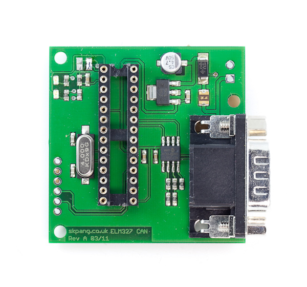
图4 - ,在许多电子设备上,CAN接口通常是标准配置。
CAN覆盖ISO/OSI协议栈的层级1和2(物理和数据链路层)。对第7层(应用层)来说,有几种替代方案。最有名的是CAL(CAN应用层,由CAN ion Automation定义)、CANopen(CAL的子集,由CiA约定)、DeviceNet和SDS。
在电子芯片中,层级1和2完全集成在硅片上。
CAN区别于其他通信系统的主要概念是其管理总线访问的方式。CAN不采用主从结构或特殊的握手机制,其行为也与采用CSMA/CD机制的以太网不同。CAN采用CSMA/CA(载波感知多路访问/冲突规避)机制,该机制支持节点在总线空闲及多个节点同时访问总线的情况下访问总线,它允许最高优先级的信息得以传送、其它信息则被叫停。
LIN
LIN是种低成本、支持全双工串行通信的串行总线。它用于车载分布式电子系统与智能传感器和执行器间的通信。LIN协议可由大多数微控制器都有的低成本UART/SCI接口实现。
LIN网络包括一个主节点和多个从节点。通讯总是由主节点发起。所有节点都可以执行通信任务,包括发送和接收。此外,主节点执行主机传输任务,它决定何时及那个帧在总线上传送。这样,就没有总线仲裁,并可以容易地计算出每个信息所需的最长时间。所有信息在总线上都以帧的方式发送。当传送一个帧后,在收到该帧及对标识符进行过滤后,只有一个从节点被激活。
在汽车行业,LIN和CAN都得到应有。CAN可用于车辆的高速和低速网络,而LIN仅用于低速网络(如车门控制单元)。通常,CAN比LIN贵,但也比LIN更可靠,但LIN可以更容易地在UART上实现。因此,LIN可能会在低速网络上取代CAN。
DeviceNet
DeviceNet是种低成本现场网络,可用以连接限位开关、光电管、阀、电机起动器、不同类型的传感器、条码阅读器、变频驱动器、操作面板和PLC等设备。这些设备与网络的直接连接提供了一种先进的通信模式以及常见的布线技术达不到的很高的诊断水平。
DeviceNet是种低成本现场网络,可用以连接限位开关、光电管、阀、电机起动器、不同类型的传感器、条码阅读器、变频驱动器、操作面板和PLC等设备。这些设备与网络的直接连接提供了一种先进的通信模式以及常见的布线技术达不到的很高的诊断水平。
DeviceNet是个“开放”标准,任何想要为该网络开发接口的人都可免费得到相关规范和协议。将第三方设备连接到DeviceNet,不必购买任何硬件、软件或许可权。希望将自己的产品连接到DeviceNet的人可从ODVA(Open Devicenet Vendor Association——开放DeviceNet供应商协会)得到规范以及一个没有限制的许可证且无任何特许权使用费。
DeviceNet基于CAN技术。目前,由于其多功能性和应用的灵活性,市面上有大量供应商提供的许多CAN芯片。
DeviceNet规范使用ISO模型的层级0、1、2和7。它描述了层级0、1和7,而由CAN来实现数据链路层。DeviceNet的主要特点是:
-最多支持64个节点
-速度:125Kbps/500米;250Kbps/250米;500Kbps/100米
-数据帧:最多8字节
-电源和信号在同一端口
-多主节点
PROFIBUS
PROFIBUS(过程现场总线)用于制造和过程自动化。PROFIBUS是种多主机系统。PROFIBUS是“单主多从”通信网络;主机(或主动器件)定义总线上的数据交互。当它拥有访问权限(令牌)时,它可在没有外部请求时,发送数据。从节点(或被动器件)不允许访问总线。它们只能发出已接收到信息的确认或在主机要求时发送信息。传输速率从9.6Kbps到12Mbps。总线最多可挂接126个设备。
通常,PROFIBUS用于连接主机(如PLC)与远程I/O。
Profibus的演绎——Profibus DP(分散式外设)是最常用的PROFIBUS协议。它可以工作在9.6kbps到12Mbps速率;在12Mbps时,节点间最长距离可达300米。
PROFIBUS PA(过程自动化)可连接31个节点;25kbps比特率时、最长距离可达1.9千米。它用于与过程仪表的通信。PROFIBUS PA与PROFIBUS DP的数据帧相同,因此可以很容易地集成PA和DP。
PROFINET
PROFINET是基于以太网的工业自动化开放标准。它使用TCP/IP协议并允许实时自动化实现。借助PROFINET,可将分散的现场设备连接到以太网、并基于这些组件建构分布式自动化系统。为了达到此目的,PROFINET分为两部分:
-用于整合分布式外设的PROFINET IO
-用于分布式自动化的PROFINET CB。
借助PROFINET IO,分布式现场设备被连接到以太网。根据被称为生产者/消费者的模型,在I/O控制器和I/O设备间交换数据:设备从外设读取信号,并将信号传送到处理这一过程的控制器。然后,控制器将输出信号传送到远程设备。
用于分布式自动化的PROFINET组件模型(PROFINET CB)是智能领域和自动化设备的理想选择。在由PCD(PROFINET组件描述)所描述的“技术模块”中,它可以组合机器内不同的自我依赖部件,且可在独立于制造商的系统架构内,实现这些部件间的通信。
在PROFINET,通信可分为三个性能水平:
1)参数和配置数据、对时限要求严格的诊断和用户数据的传输是通过TCP/IP或UDP/IP完成的。
2)对时间要求严格的过程数据,可采用实时(RT)信道。它是在现有以太网控制器上用软件创建的。
3)对于运动控制应用,它提供了一种实时同步(IRT)通信,在1ms的速率下,允许1μs的抖动。
基金会现场总线
使用现有的标准和测试技术,基金会现场总线业已开发出一种专门以过程控制为目标应用的现场总线。
基金会现场总线满足了过程控制应用对分布式控制“鲁棒性”的要求。其技术包括物理层、通信协议栈和用户应用。因此,基金会现场总线,并没有实现ISO模型的3、4、5和6层,因为在过程控制应用中不需要这些层级所对应的服务。但它增加了一个第八级:用户应用层。
在基金会现场总线中,已针对过程控制,对ISO/OSI架构进行了优化,它拿掉了通常伴随非关键应用(如文件传输)的中间层级。剩下的三个层级是:物理(层级1)、数据(层级2)和应用(层级7)。
AS接口
AS-interface (As-i) 是一种用于开/关或模拟传感器和执行器的低成本现场总线连接,它是自动控制机柜和现场I/O间平行布线的一种替代方案。
 is one of the simples.jpg)
图5 - AS-I(执行器传感器接口)是连接传感器和执行器的最简单现场总线,
AS-I是一个开放、独立于制造商的标准。任何传感器和执行器的制造商或用户都可通过AS-i协会得到AS-i规范和配置文件,它们分别保证了系统的互操作性和产品的互换性。
可从市场上随意买到支持AS-i通信的芯片。
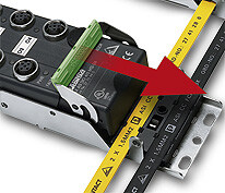
图6 - 连接到AS-i总线很简单。
AS-i总线的一个显着特点是传输介质:一条简单的屏蔽铜绞线。AS-i采用的数据传输方法(APM——替代脉冲调制)对电磁干扰有很强免疫力。
AS-I是主/从系统。一个主机可连接31个双向从机(带4输入/4输出),以实现最多248个数字I/O。主机和从机间的信息有固定长度。传输速率为167kbps。主机需要5ms轮询31个从机(或1ms轮询6个从机)。市场上有很多用于连接AS-i与上层总线(如Profibus、DeviceNet和CAN等)的网关。
结论
市场上还有许多其它种现场总线。它们通常可分为:标准总线;事实上的标准总线;专属总线。此外,目前还使用许多基于以太网的协议。
选择最合适的现场总线必须始终从应用开始:例如,为楼宇自动化推出的现场总线,理论上也可以用于工业自动化。但市场上,可能没有针对此类应用的设备。因此,与工业自动化、过程控制和运动控制等一样,楼宇自动化也有其自己的总线。
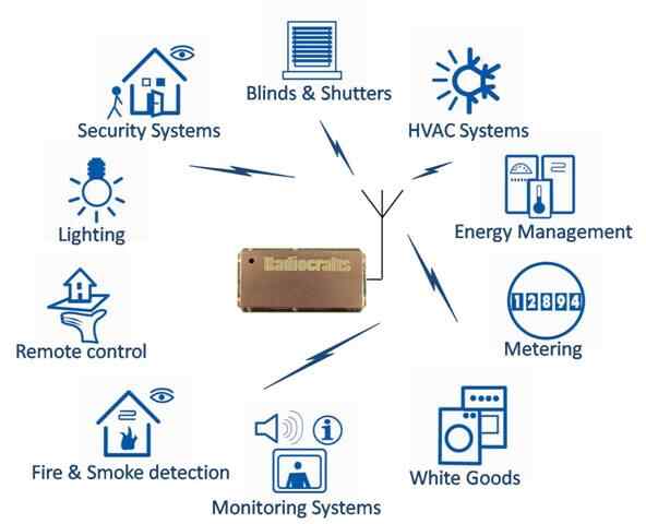
图7 - KNX是广泛用于楼宇自动化应用的现场总线
其他的选择标准涉及本地支持:选择一个当地机构不支持的现场总线,并非明智之举。事实上,如果该用户需要帮助,没有人会回应其请求。
最后,高瞻远瞩始终是上策:其性能足以满足当前应用需求的现场总线,在未来,若应用需求增加,则就可能变得差强人意。
Fieldbuses and Industrial Networks
[member]
Fieldbuses and Industrial Networks
Fieldbuses are industrial communication systems that, using either cables, optical fibres or radio waves for signal transmission, connect field devices to a central control system. Fieldbus technology was developed in the 80s to replace traditional cabling systems and the analog transmission of signals with digital technologies. Moreover, fieldbuses create the basic framework for designing distributed control systems.
Valerio Alessandroni
Fieldbuses are communication systems allowing distributed control, supervision, detection and command devices to be interconnected.Thanks to this technology, sensors, electrovalves, programmable controllers,electronic drives, computers, etc. can easily exchange information using a single low-cost connection. And this exchange occurs independently from the manufacturers of single devices.
Fig. 1 – Many kinds of devices can be connected to a fieldbus to exchange data.
Note: Marcatori laser = Laser markers, Servoazionamenti = Servodrives, Sistemi di polimerizzazione = Polymerization systems, Unità wireless = Wireless units, Termoregolatori = Thermoregulators, PLC ultra-compatti = Ultra-compact PLCs, Pannelli operatore = Operator panels, Sensori fotoelettrici = Photoelectric sensors, Ionizzatori = Ionizers, Sistemi di visione = Machine vision systems, Sensori laser = Laser sensors, Barriere di sicurezza = Safety barriers
The concept of fieldbus is not new, but in recent years it became very popular due both to the increase of the commercial offer and because the users have understood the clear strategic value that this technology represents.
Why this explosion of interest? Largely because the market requires the possibility of using different products without any commercial or technological limitaion. The suppliers themselves have understood the usefulness of a common environment: when a products is provided with a standard interface, it means that it can be available to a much wider market.
The word ‘field’ reminds something that is geografically and contextually delimited. This is true also in ‘fieldbus’ definition, at different abstraction levels. On the other hand, ‘bus’, is a typical word from computer science world that indicates a group of conductors connecting different cicuits allowing them to exchange data. A fieldbus, therefore, is a communication system whose purpose is to connect multiple distributed devices, that are actively participating to data exchange.
Generally, fieldbuses allow to transfer data in serial mode, one bit after the other. The advantage of this choice is that a significantly smaller number of electric conductors is required (normally, fieldbus cables have only three conductors).This allows to cover big distances with low costs.
The correct operation of the communication system requires that the fieldbus is accessed following strict rules, so that the information stream can circulate from producer to consumer. The set of these rules is called ‘protocol’.
Fig. 2 – Like all standardized communication networks, also fieldbuses adhere to the ISO/OSI stack.
There are basically two arguments in favour of fieldbuses:
- The communication through a fieldbus allows an information exchange that would be difficult otherways
- The information exchange occurs following a standardized mechanism
Starting from these two points, other arguments were generated, that are now widely used in commercial way:
- The network based on fieldbus can be easily scaled
- Products of different manufacturers can dialogue
- It is possible to cover greater distances
- The cabling and overall costs are drastically reduced
- The application fields are greater
- The installation is simplified
- The engineering costs are reuseable
- The market offers monitoring and commissioning tools that make these tasks easier
But also some disadvantage should be mentioned:
- A deeper know-how is required
- A greater investment is required in esquipment(equipment?) and instruments
- Higher starting costs
- The compatibility between devices of different manufacturers is not always sure, though the use of common standards.
Concerned industries
To-day, everybody is concerned with fieldbuses. In cars, for instance, they are used to simplify the cabling and add functionalities to basic controls. But this example shows that, in the end, the final user is not really concerned about the fieldbus that has been actually used.
Besides the final user category, anyway, there are other two categories of professionals concerned:
- System integrators that, using devices able to communicate through fieldbuses, have to afford commissioning problems
- Developers of devices or communication interfaces for fieldbuses, that have to afford problems of electronic development and adequate software
The approach of these two categories is different. To the first catogory it is important to have tools that make commissionin and diagnostics easier. Moreover, it is preferable that the fieldbus is easy to use. To the secondo catogory, on the pther hand, it is more important to easily find the electronic components that allow the maximum simplification of developement, both of the electronic circuits and of the software managing the communication.
Fieldbus classification
Before selecting the communication network to be adopted for a given problem, it is useful to perform an analysis, possibly independent from commercial influences. The ‘pyramid’ model offers a practical contribution to this task.
In an ideal plant there are multiple levels of data management. For each level the requirements are differents. For instance, administration often manages volumes of data that can be quantified in megabytes, but response times are not critical (being of the magnitude order of minutes, hours and even days).
But in working shops and in production areas, that are the main destinations of fieldbuses, there are more limitations: in lowest levels, to consider the opposite end, few bytes must be transferred in few microseconds.
The following levels of communication are normally defined:
- Level 0: ‘sensor/actuator’ bus
- Level 1: fieldbus
- Level 2: cell bus
- Level 3: local area network (LAN)
- Level 4: wide area network (WAN)
Fig. 3 – The positioning of fieldbuses within the plant architecture: fieldbuses normally concern levels 0, 1 and 2.
These differences represent the selection criteria of a fieldbus type. In general, for a given application it’s easy to quantify parameters like the response time and the quantity of data that can be sent.
The fieldbus category concerns only the lowest levels of the ‘pyramid’ model. This category includes all the buses that can transmit data frames spanning from some bits to some hundreds of bytes. The fieldbus category can be furtherly divided into 3 main groups:
- Real fieldbuses
- ‘Sensor/actuator’ buses, dedicated to I/O signal interconnection (‘multiplexer’ function)
- Application-specific buses (for instance, motion control buses like Sercos, building automation buses like LON, automotive buses like LIN, etc.)
The real fieldbuses are used to connect smart units co-operating in a process. Being the applications at this level generally structured in a hierarchical way, most fieldbuses of this class communicate following the ‘master-slave’ principle: a main node acts as a ‘master’ of the network, while all the other nodes are ‘slaves’. Only the master can start a data exchange. A slave must wait to be polled and, at that time, it has to answer with proper data. Though this leads to a great simplicity of use, the master-slave architecture has a drawback: if the master doesn’t work, everything is blocked. For this reason, modern fieldbuses can manage the transfer of the master function to another node of the network.
At the lower level, ‘sensor/actuator’ buses limit themselves to connect a small number of ‘smart’ nodes to non-programmable distributed nodes that are simple I/O signal collectors or have predefined functions. A classical application is the scattering of a PLC I/O’s. In this case, the programmer doesn’t have to care about the communication through the bus, because the communication is fully managed by the operating system of the PLC.
Industrial automation fieldbuses
In industrial automation many fieldbuses are used, as it is understood that a single standard fieldbus can’t cover all the requirements of this sector. Below, some of the most popular are shortly described.
Modbus
Modbus is a serial communication protocol created by Modicon in 1979 for its own programmable controllers (PLCs). It is now a de-facto standard in industrial communication and the most popular linking protocol among industrial electronic devices. The main reasons of this success are:
1.It is a royalty-free protocol, freely accessible
2.Can be implemented very quickly
Two versions of the protocol are available: one on serial port (RS232 by default, but also RS485) and one on Ethernet.
CAN
CAN (Controller Area Network) belongs to level 0 buses, i.e. sensor/actuator buses. It is a serial communication system originally designed for automotive applications by Bosch and Intel. The purpose was to reduce the electric cabling in vehicles, while improving the layout flexibility and the security of information transport.
To-day, CAN is also used as a fieldbus for industrial applications. Its popularity is mainly due to the large amount of Ics that implement its functionalities.
Fig.4 – A CAN interface can be found by default on many electronic devices.
CAN covers levels 1 and 2 (Physical and Data Link Layer) of ISO/OSI stack. For level 7 (Application Layer) several alternatives are available. The most known are CAL (CAN Application Layer, defined by CiA – CAN ion Automation), CANopen (a subset of CAL, specified by CiA), DeviceNet and SDS.
In electronic chips, both level 1 and il level 2 are fully integrated on silicon.
The main concept that differentiates CAN from other communication systems is the way CAN manages bus access. CAN doesn’t have a master-slave structure or a special handshaking, nor it behaves like Ethernet with CSMA/CD mechanism. CAN uses CSMA/CA (Carrier Sense Multiple/Access / Collision Avoiding) mechanism, that allows to access the bus when it’s free and, in case of simultaneous access by multiple nodes, allow the message of highest priority to be forwarded, while the other messages are interrupted.
LIN
LIN is a low-cost serial bus that supports full-duplex serial communications. It is used for distributed electronic systems onboard of vehicles, for communications with smart sensors and actuators. LIN protocol can be implemented on the common low-cost UART/SCI interface that is available on most microcontrollers.
LIN network includes a master and multiple slaves. The communication is always started by the master. All the nodes can execute the communication task, that includes the transmission and reception tasks. In addition, the master executes the master transmission task, that decides when and which frame to transfer on the bus. In this way, there is no arbitration on the bus and it’s easy to calculate the worst time for every message.All messaghes are sent on the bus as frames. When a frame is transmitted, only one slave is activated after the reception and the filtering of the identifier.
In automotive industry, both LIN and CAN are used. CAN is used for high and low speed networks in the vehicle, while LIN is used only for low speed networks, like door control units. Generally, CAN is more expensive but also more reliable than LIN, but LIN can be easier implemented on an UART. Therefore, LIN will probably replace CAN in low-speed networks.
DeviceNet
DeviceNet is a low-cost field network to connect devices like limit switches, photocells, valves, motor starters, sensors of different kind, barcode readers, variable frequency drives, operator panels and PLCs. The direct connectivity of these equipment to the network offers an advanced communication mode and a high diagnostic level that can’t be reached through common cabling technologies.
DeviceNet is an ‘open’ standard: the specification and the protocol are available to anybody wants to develop interfaces for this network. No hardware or software or license rights must be bought to connect third-party equipment to DeviceNet. Who wants to connect his products to DeviceNet receives the specification from Odva (Open Devicenet Vendor Association), together with a no-limits license, without royalties.
DeviceNet is based on CAN technology. CAN chips are to-day very popular, due to their versatility and application flexibility, and are offered by a large number of suppliers.
DeviceNet specification uses levels 0, 1, 2 and 7 of ISO model. It describes levels 0, 1 and 7, leaving to CAN the implementation of DataLink Layer. The main features of DeviceNet are:
-Number of nodes: up to 64
- Speed: 125 Kbps up to 500 m, 250 Kbps up to 250 m, 500 Kbps up to 100 m
-Data frame: up to 8 bytes
-Power and signal on the same support
-Multimaster
Profibus
Profibus (Process Field Bus) is used in manufacturing and process automation. Profibus is a Multi-Master system. Profibus is a monomaster-multi slave communication network The Master, or active device, defines the data traffic on the bus. When it owns the access permission (Token) it can send data without external request. The Slaves, or passive devices, have no access permession to the bus. They can only acknowledge the reception of messages or send messages when required by the Master. Transfer speed varies from 9,6 kBaud to 12 MBaud. Up to 126 devices can be connected to the bus.
Generally, Profibus is used to connect a master, like a PLC, to remote I/Os.
The variant Profibus DP (Decentralized Peripherals) is the most used Profibus profile. It can operate at bit rates from 9,6 kbps to 12 Mbps on distances between nodes up to 300m at maximum speed.
Profibus PA (Process Automation) works with bit rates up to 31,25 kbps for a maximun distance of 1.9 km. It is used for communications with process instruments. The data frame of Profibus PA is the same of Profibus DP, therefore the integration of PA and DP is very easy.
Profinet
Profinet is an Ethernet-based open standard for industrial automation. It uses the TCP/IP protocol and allows real-time automation. With Profinet is is possible to connect scattered field devices to Ethernet and tocreate distributed automation systems based on components. To this purpose, Profinet is divided in two parts:
- Profinet IO for the integration of distributed peripherals
-Profinet CB for distributed automation.
With Profinet IO, distributed field devices are connected to Ethernet. Data exchange is performed between I/O controllers and I/O devices according to a model called Producer/Consumer: a device reads signals from periphery and transmits them to a controller that process the signals. The controller then transmits output signals to remote device.
The model of Profinet components for distributed automation (Profinet CB) is ideal for smart field and automation devices. It allows to combine different self-dependent parts of a machine in ‘technological modules’ that are described in a PCD (Profinet Component Description) and can communicate between them in system architectures that are manufacturer-independent.
In Profinet, communications can be classified in three performance levels:
1) Transmission of parameters and configuration data, time-critical diagnostics and user data is via TCP/IP or UDP/IP.
2) For time-critical process data a Real-Time (RT) channel is available. It is software created on an existing Ethernet controller.
3) For motion-control applications a Real-Time Isochonous (IRT) communication is available, allowing a jitter of 1 μs at a rate of 1 ms.
Foundation Fieldbus
Fieldbus Foundation has developed a fieldbus specifically oriented to process industry using existing standards and tested technologies.
The Foundation Fieldbus responds to the requirement of a ‘robust’ distributed control for process control applications. Its technology includes the physical level, the communication stack and the user application. Theretore, Foundation Fieldbus doesn’t implement levels 3, 4, 5 and 6 of ISO model, because the services of these levels are not required in process control applications. Anyway, it adds an eighth level: the user application level.
In Foundation Fieldbus, the ISO/OSI architecture has been therefore optimized for process control, removing the intermediate levels that are generally associated to non-critical applications, like file transfers. Three levels remain: Physical (level 1), Data (level 2) and Application (level 7).
AS-interface
AS-interface (As-i) is a fieldbus for the low-cost connection of on/off or analog sensors and actuators as an alternative to parallel cabling between automation cabinet an field I/Os.
Fig. 5 - AS-i (Actuator Sensor interface) is one of the simplest fieldbuses, used to connect sensors and actuators
AS-i is an open and manufacturer-independent standard. Any manufacturer or user of sensors and actuators can obtain AS-i specifications and profiles, that respetively ensure the system interoperability and the product interchangeability through AS-i association.
The chip on which AS-i communication is based is available on the market without any restriction.
Fig. 6 – Connection to AS-i bus is very simple.
A distinguishing feature of AS-i bus is the transmission support: a simple unshielded copper pair. The data transmission method used by AS-i (APM, Alternate Pulse Modulation) allow a hight EMI immunity.
AS-i is a Master/Slave system. It is possible to connect a single Master and 31 bidirectional Slaves (with 4 inputs and/4 outputs) for a total of 248 digital I/Os. Messages between Master and Slaves have a constant length. Transfer rate is 167 kbit/s. The Master requires 5 ms to poll 31 Slaves or 1 ms for 6 Slaves. Many gateways are available on the market to connect AS-i to upper level buses (like Profibus, DeviceNet, CAN, etc.).
Conclusion
Many other fieldbuses are available on the market. Generally, they can be classified into standard, de-facto standard and proprietary buses. Moreover, many Ethernet-based protocols are used to-day.
The selection of the best fieldbus must always start from the application: a fieldbus that was introduced for building automation, for instance, can be theoretically used also for industrial automation. But. On the market, no devices will be available for such application. Therefore, building automation has its own buses, like industrial automation, process control, motion control, etc.
Fig. 7 – KNX is a fieldbus widely used in Building Automation applications
Other selection criteria concern the local support: it is not a good practice to select a fieldbus that is not supported by a local organization. In fact, if the user needs help, nobody will answer to his requests.
Finally, it is good to always think to the future: a fieldbus whose performances are enough to satisfy current application requirements could become unsatisfactory if the application requirements increase in the future.


 is one of the simples.jpg)


